
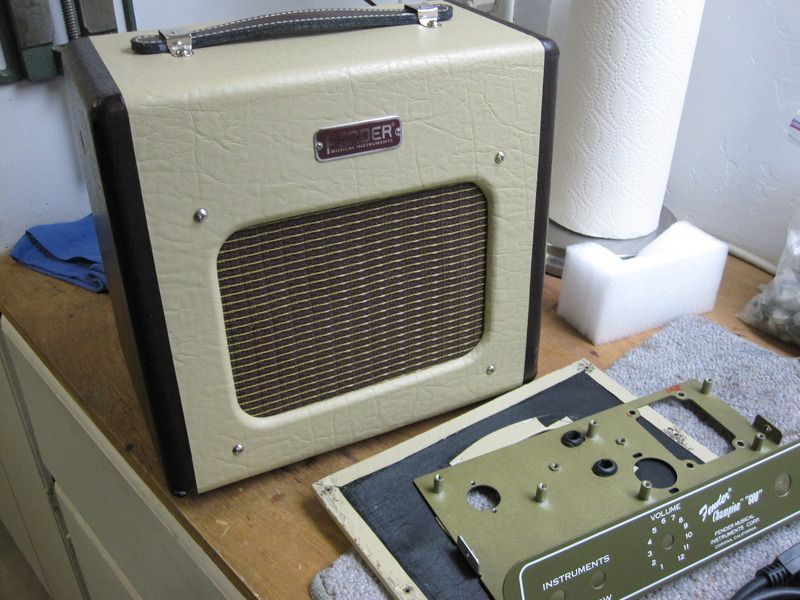
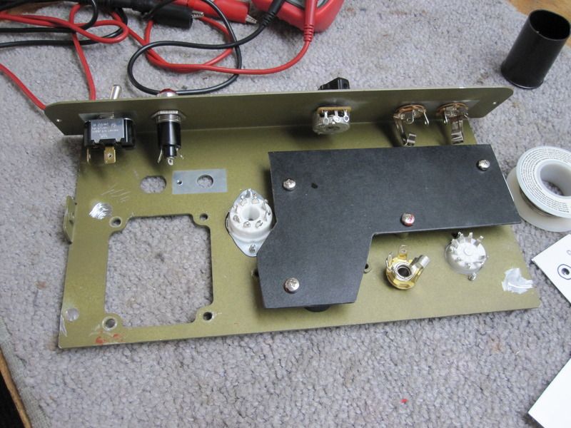
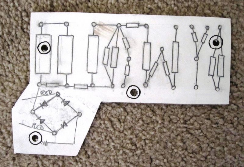
Fabricating the circuit board out of left over Bakelite material fron another project. Will be drilling and installing eyelets
Mr. Bill wrote:
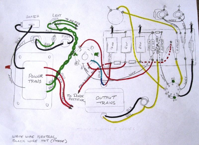
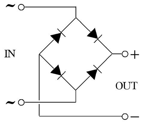
I just looked at the layout for the filaments, you will either need to add two 100 ohm resistors to create a ground reference or ground one side of the filaments and have the other side at 6 vac. If you don't the amp will hum like crazy.

Return to “Amp Tech Q&A and Repair Shop”
Users browsing this forum: No registered users and 40 guests